Conversation
|
|
|
|
|
|
|
Hi David, thanks for your expanations. They helped me connecting lcd and sd. I bought the same board and now I am struggling compiling Marlin 2.0 for it. Are you using Marlin too? I managed to compile without EEPROM useage - I had to disable it in src/MarlinCore.cpp inside the setup function. Same with USE_WATCHDOG. Trying to debug the watchdog problem, I found out that it uses the watchdog.cpp inside the src/HAL/STM32 directory, instead of the one inside the src/HAL/STM32_F4_F7 directory. I did not find out how to change that yet. Do you have any advise for me? Did you manage to compile and use Marlin 2.0 with EEPROM and USE_WATCHDOG? Best Regards, |
|
Hi Boris,
I haven't managed to get the EEPROM working yet. I am buidling under VS Code and Platformio.
I realised that the EEPROM needs one of the I2C voltages to be configured on the back of the board in the "I2C-VCC" pads which I had not done. I think I tried 3.3V to play safe but it still didn't work. I have been meaning to try the other voltage selection but not got around to it yet as it is so tricky to get to on my system.
I haven't come across your watchdog issue yet. Perhaps that's why my sytem keeps hanging mid print. Not had much oportunity to work on it.
It's a real shame the author isn't responding or contactable
Regards
David
…On 13 December 2020 at 13:56:56 -00:00, BorPass ***@***.***> wrote:
Hi David, thanks for your expanations. They helped me connecting lcd and sd. I bought the same board and now I am struggling compiling Marlin 2.0 for it. Are you using Marlin too?
I managed to compile without EEPROM useage - I had to disable it in src/MarlinCore.cpp inside the setup function. Same with USE_WATCHDOG. Trying to debug the watchdog problem, I found out that it uses the watchdog.cpp inside the src/HAL/STM32 directory, instead of the one inside the src/HAL/STM32_F4_F7 directory. I did not find out how to change that yet.
I guess it is a similar problem with the EEPROM problem, because the STM32F4 chips should have build in EEPROM.
Do you have any advise for me? Did you manage to compile and use Marlin 2.0 with EEPROM and USE_WATCHDOG?
Best Regards,
Boris
—
You are receiving this because you modified the open/close state.
Reply to this email directly, view it on GitHub <#4 (comment)>, or unsubscribe <https://github.com/notifications/unsubscribe-auth/ABVHAFVEATE47V7T57QN3PTSUTB2RANCNFSM4MDET4FQ>.
<http://www.avg.com/email-signature?utm_medium=email&utm_source=link&utm_campaign=sig-email&utm_content=emailclient> Virus-free. www.avg.com <http://www.avg.com/email-signature?utm_medium=email&utm_source=link&utm_campaign=sig-email&utm_content=emailclient>
|
|
Hi David, thanks for your reply. It was a motivation for me to keep on trying to get the board running as exspected. I think I got the EEPROM working now, without soldering anything. Looking through Marlin code, I thought there could be missing a #define ARDUINO_ARCH_STM32 I included this into Configuration.h right under the board definition, which now looks like that: #ifndef MOTHERBOARD Now it compiles with eeprom-support and I am able to read the settings with M503. This should be proof enough, that it works. Next construction-site will be the WATCHDOG, which makes my board reboot, when the 4s, specified in the code, run out. Perhaps the reason is that I run it offline, outside the printer without sensors etc., but I don‘t think so. I will let you know, if I find out. Regards Boris |
|
Hi David, I was wrong, EEPROM doesn‘t work. I also tried supplying 3.3V to the vcc-i2c pin without success. Perhaps one has to set a jumper to the 3.3/5V i2c-vcc area, which would mean soldering pins first. But I am not microelectronic professional... |
|
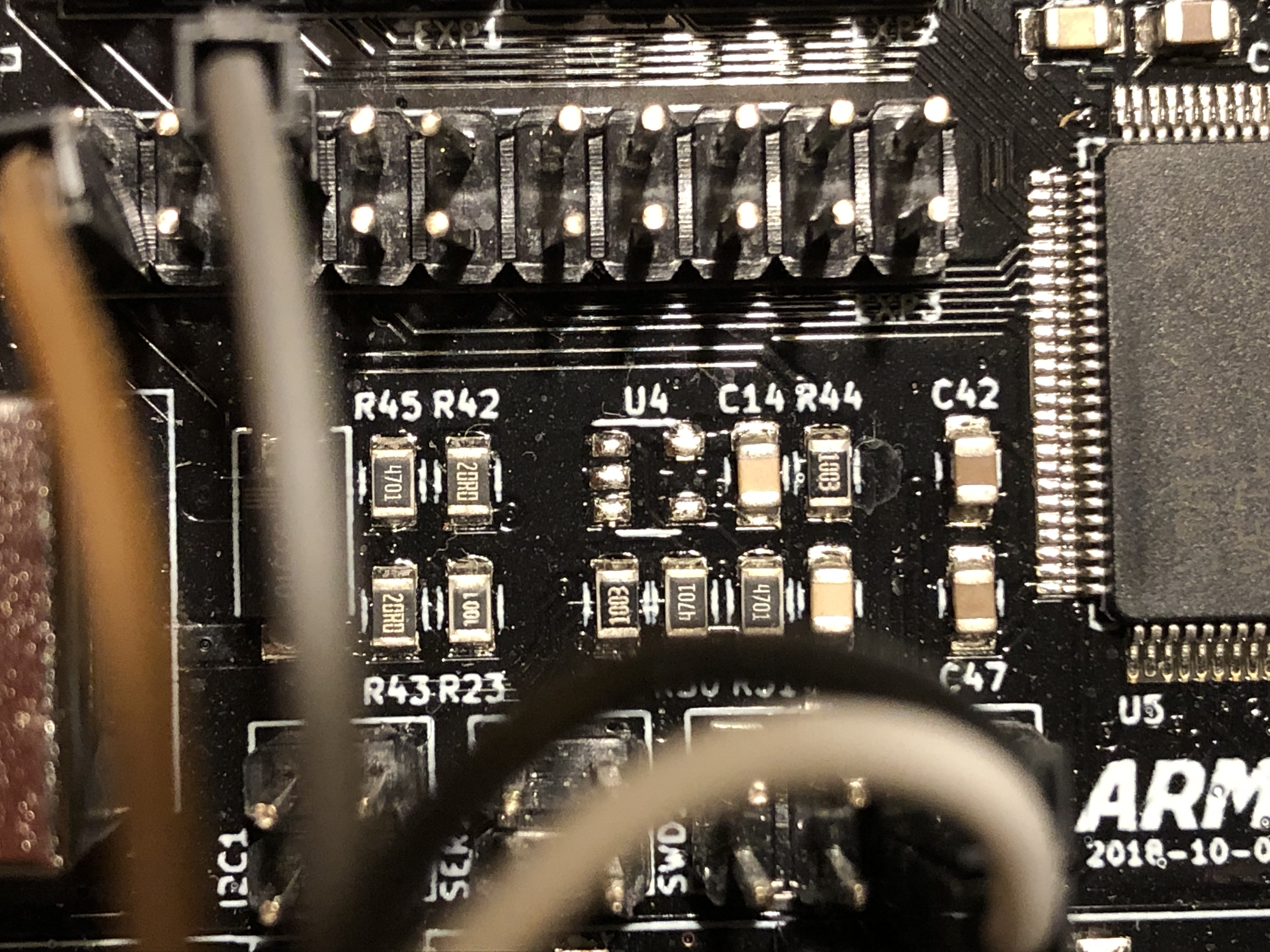
Hi David, I might be wrong, but on my board there is probably missing a chip in the location marked as U4. Following the electrical lines from the i2c section this might be the position of the eeprom. Do you have a chip at position U4? In some pictures, e.g. the ones from Karl, the designer, I mean to see one, on other like amazon the place is empty like on mine. |
|
Hi Boris, U4 is the 24LC32AT EEPROM and I "think" there is a device soldered there on my board. It's hard to tell as I can't get my phone to focus on the board past my cables. I only have detailed photos of the back of my board before it was installed. I figured the ones from websites were good enough for reference of the front. |
|
U4 is the eeprom and it is required if external eeprom is used in Marlin.
You might get it to work without it if you run emulated eeprom or whatever
it is called in Marlin.
Den tis 29 dec. 2020 kl 13:19 skrev David <notifications@github.com>:
… Hi Boris, U4 is the 24LC32AT EEPROM and I "think" there is a device
soldered there on my board. It's hard to tell as I can't get my phone to
focus on the board past my cables. I only have detailed photos of the back
of my board before it was installed. I figured the ones from websites were
good enough for reference of the front.
This is the board I purchased:
https://www.amazon.co.uk/gp/product/B081RJ46CN/ref=ppx_yo_dt_b_asin_title_o01_s00?ie=UTF8&psc=1
The other day I took a copy of Karl's latest Marlin 2.0.7.2 changes and
merged some of his configuration settings with mine. Prior to this I was
getting some EEPROM init errors. Now I can store and load settings without
errors but they don't seem to be being stored. I have, however, lost my USB
comms to PC so there might be errors/warnings being reported that I can't
see on LCD.
—
You are receiving this because you are subscribed to this thread.
Reply to this email directly, view it on GitHub
<#4 (comment)>, or
unsubscribe
<https://github.com/notifications/unsubscribe-auth/AEHQ2JDWJLMQDV4P2CMACCLSXHCNHANCNFSM4MDET4FQ>
.
|
|
Hi David and Karl,
|
|
Dear Karl an David, I soldered an EEPROM, now everything seems to work. It reads and stores data. Now there is one more question: How do I connect my BLTOUCH? Any hint is wellcome! Best Regards and a happy new year, |
|
glad you got your EEPROM working. I will need to pull my board out of the housing to check if I have chip in U4 or not. Sorry, I can't help with your probe servo as I use an inductive sensor |
|
Hello David and Karl, |
|
Hi Boris, Glad you got your EEPROM working and probe servo working. I need to look into the TMC2208 drivers. I am using the TMC2130's in SPI mode with the end-stop detection pin wired to X and Y. I am getting some layer shift on the Y axis though. It may print about 1cm Z height okay and then the Y axis jumps about 10mm. I am also seeing my driver currents keep reducing due to thermal protection - lots to sort out |
|
Hey David, |
I had difficulty obtaining information for this board and hope my notes will be useful to someone else.
I too downloaded the authors KiCad project but was unable to see the schematic clearly due to missing libraries that only exist (to my knowledge) on the author's development PC.
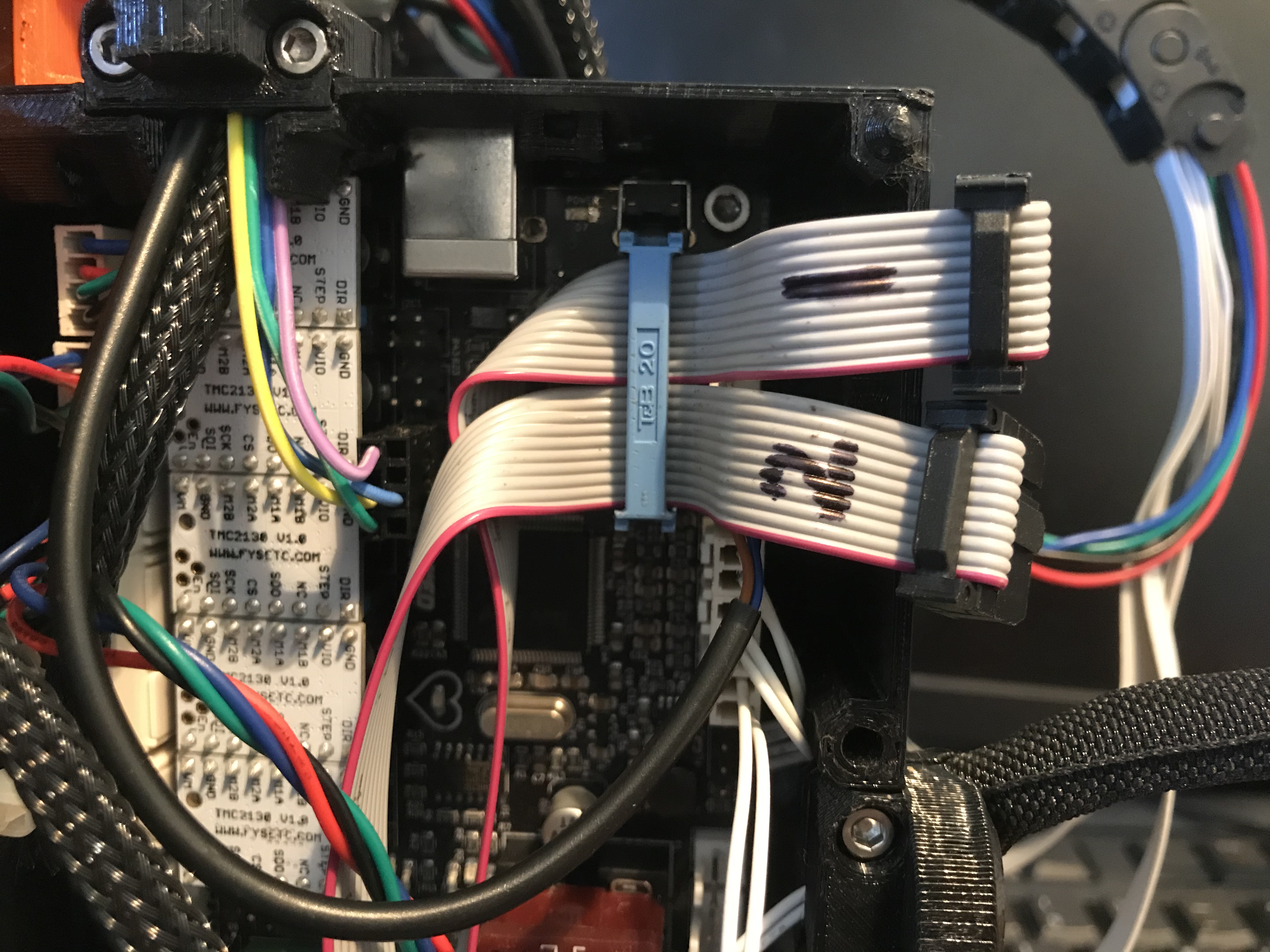
I was able to reverse engineer the pins for the exp1 and 2 connectors. These seem to be rotated 180 degrees from what I normally find on similar RAMPS 1.4 LCD adapter boards. One of my images shows how I merged Exp1 and Exp 2 cables into a single 20 pin IDC connector. To do this I put tape across the two ribbon cables either side of where the connector was to be installed.
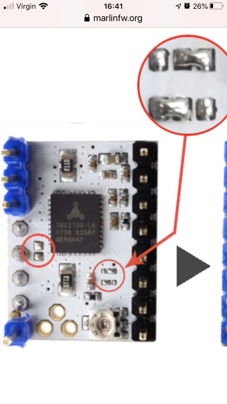
The image of the TMC2130 driver shows how the SPI bridge (on left) needs to be open and how CFG 4 and CFG 5 (on right) need to be bridged. I had to remove a small zero ohm resistor from my drivers to get the SPI talking. However, the FSYETC TMC2130 drivers that came for my board also needed bridges for CFG4 and CFG5 to be made. These are incredibly small bridges to make by hand. Of my 5 drivers I was only able to configure 1 correctly. I have since ordered 5 more drivers that are already pre-configured
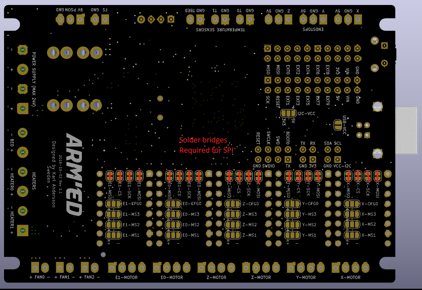
I also had to bridge all of the SPI solder bridges on the back of the ARM'ED board (-MOSI, -SCK, -CS, -MISO) for SPI. At the moment I do not know if the -CFG0 bridges need to be made?